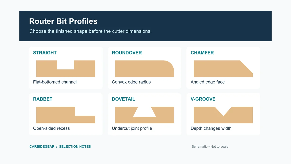
Router bit types should be chosen by the shape they leave in the workpiece, then by how the cut will be guided and whether the cutter fits your router. A straight bit makes a flat-bottomed channel; a roundover softens an outside corner; a flush-trim bit copies a reference edge. The shank, bearing position, cutting reach, and operating limits still have to match the setup.
If your projects need several common profiles, compare router bit sets with the profiles and shank sizes you need. For a single task, buying the correct individual geometry is often more useful than adding unrelated cutters to a set.
Router Bit Types by Finished Shape
The most useful bit description is a combination of result and constraint: “a rounded edge with this radius,” “a recess that fits this hinge,” or “a flush edge copied from a template above the board.” That is more precise than choosing by the color of the cutter or the number of pieces in a case.
| Desired result | Cutter family | First detail to confirm |
|---|---|---|
| Flat-bottomed groove or pocket | Straight or suitable spiral bit | Cutting diameter, usable depth, and entry capability |
| Edge copied from an existing shape | Flush-trim or pattern bit | Bearing location and continuous reference surface |
| Rounded outside corner | Roundover | Profile radius and remaining stock |
| Angled edge | Chamfer | Angle and achievable bevel width |
| Broad flat surface | Surfacing or spoilboard cutter | Spindle compatibility, diameter, and clearance |
| Rounded-bottom recess | Bowl-and-tray bit | Bottom radius and ability to enter the cut |
| Narrow decorative line | V-groove or engraving cutter | Included angle, tip geometry, and depth |
| Mating joint | Joint-specific geometry | Actual stock thickness and matching dimensions |
These are geometry groups, not universal operating instructions. Two cutters in the same family can require different entry methods, speeds, support, and machines.
Read the Dimensions Before the Product Name
The shank diameter is the part held in the collet. It is different from the cutting diameter. A bit with a 1/2-inch cutting diameter can have a 1/4-inch shank, so the product’s largest printed dimension does not establish whether it fits. A 1/4-inch collet and a 6 mm shank are not interchangeable sizes.
Cutting length describes the length of the active edge, while overall length includes the shank. The usable reach can be shorter than either figure once proper insertion, the router base, a template, and the workpiece are considered. Do not gain extra reach by pulling the shank out beyond the specified clamping position.
For a profile bit, radius or angle defines the finished shape. For a bearing-guided cutter, bearing position and diameter affect where the reference surface must be and what offset the cutter leaves. Record those fields separately rather than reducing the purchase decision to “large” or “small.”
Flush-Trim and Pattern Bits: Follow the Reference
A flush-trim cutter removes an overhang until the cut aligns with a reference surface. In a typical template setup, the bearing follows the template while the cutting edges remove the protruding workpiece. The template must be firmly fixed, smooth, and thick enough for the bearing to remain supported throughout the cut.
Bearing location is a practical selection filter. A bearing nearer the shank can follow a template on the router side of the work; a bearing near the cutter tip follows a reference farther from that side. Inverting the router in a table changes the physical orientation, which is why “top bearing” should be checked against the actual tool drawing. Our flush-trim router bit guide separates bearing arrangements and cutting reach.
Imagine a template sitting on top of a board under a handheld router. A tip-mounted bearing cannot automatically follow that upper template just because the bit is labeled flush-trim. Sketch the template, board, bearing, and cutter before deciding which configuration reaches the reference.
Roundovers and Chamfers: Radius Is Not Bevel Width
A roundover produces a curved edge. Its radius is a design dimension, not the amount of material removed in every direction. The cutter height, bearing contact, and stock thickness influence whether the result is a simple softened corner or includes a small shoulder. Choose roundover bits by profile radius and bearing arrangement when the curve must match existing trim or another part.
A chamfer produces an angled face. Its angle does not tell you the maximum bevel width: cutter size, adjustment, and remaining material also matter. For example, a 45-degree chamfer can create a modest edge break or a wider decorative face, within the bit’s supported range. Compare chamfer router bits with the required angle and cutting size when that flat bevel is the intended result.
Do not use a roundover and a chamfer as substitutes merely because both remove a sharp corner. The visible profiles and the amount of wood left around a joint are different.
Surfacing and Bowl Cuts Need Different Geometry
A surfacing cutter sweeps a broad flat area. Its large diameter changes the demands on spindle speed, clearance, workholding, and machine rigidity. A spoilboard cutter listed for a CNC spindle is not automatically suitable for a small handheld trim router. The router bits for flattening slabs and spoilboards guide is the relevant next step once the machine and required cutting width are known.
A bowl-and-tray cutter combines a flatter floor with a rounded transition, depending on the specific profile. It is used to form a recess rather than simply sweep a plane. Check whether the cutter can plunge or needs another entry method, and whether a bearing is included for template guidance. Our bowl-and-tray router bit selection focuses on those recess-making features.
On either task, a broad cutter does not justify a full-width, full-depth pass. Use the tool maker’s operating guidance for the cutter and the machine instead of borrowing settings from a smaller straight bit.
Hardware Recesses, Keyholes, and Inlays
Hinge mortises need the correct footprint and depth. A round cutter leaves rounded internal corners; square-corner hardware may require another finishing step. Compare hinge-mortising router bits for the recess and template after identifying the hinge thickness and guide system. Cutter diameter alone does not account for a guide-bushing offset.
A keyhole cutter forms an undercut slot that can capture a suitable screw head. The entry opening, neck width, depth, and screw geometry work together. It is not a straight bit that can be lifted out anywhere along a narrow slot. The keyhole router bit guide helps match the cutting geometry to the intended hanger arrangement.
Inlay kits may combine a straight cutter, guide bushing, removable collar, and sometimes a template. Their fit depends on the relationship between those components. Mixing a cutter from one system with an unrelated collar changes the offset. Review router inlay kits with matched cutting and guide hardware when choosing the whole system, rather than treating every included component as another router bit.
CNC Profiles: Flat, V-Shaped, Rounded, and Plastic-Cutting
For lettering, a V-shaped cutter makes a groove whose width changes with cutting depth. A steeper or wider included angle changes the geometry, and the actual tip may be pointed, radiused, or truncated. Our sign-making router bit guide covers those profile choices. A bit that looks pointed in a photograph is not enough to set the tool geometry in CAM.
For mixed CNC woodworking, CNC router bit sets can provide several geometries, but each tool still needs its own tool-library entry. Record shank, cutting diameter, cutting length, flute geometry, and the correct tool type. A nominal ball diameter is not the same field as the tip diameter of a tapered ball-nose cutter.
Rounded tips can reach curved surfaces and small sculpted details, with finish affected by the tool shape and stepover. Compare CNC bits for 3D carving for those operations. This is a woodworking/CNC routing branch; it does not establish that the same tool is suitable for machining steel or titanium.
Plastic routing adds another constraint: the exact polymer and chip-removal behavior. A suitable single-flute or O-flute design can be useful, but “plastic” is not one uniform material. Select CNC router bits for the specific plastic and cutting operation after checking the manufacturer’s material application. Melting is a reason to examine geometry, chip removal, sharpness, and cutting parameters together.
Cabinet-Door Profiles Must Match the Frame and Panel
A flat-panel Shaker door and a raised-panel door need different profiles. The frame groove, rail-end joint, panel tongue, stock thickness, and reveal must work as a system. A panel can have the right overall size and still fail to seat in the groove because its edge profile is wrong.
Use Shaker cabinet-door router bits for the intended frame-and-flat-panel arrangement. For a profiled panel edge, examine raised-panel router bits and the required router-table setup. A large horizontal panel cutter and a vertical panel cutter cannot be chosen on appearance alone; diameter, workpiece support, and permitted machine use differ.
Separate Shape, Joint Fit, and Spiral Direction
The profile tells you the shape, but mating parts need another set of decisions. Use the woodworking-joint router bit guide for groove width, rabbet dimensions, dovetail-jig fit, and tongue-and-groove alignment.
Spiral direction is a separate selection layer. Two cutters with similar diameters can move chips and affect the visible face differently. The upcut, downcut, and compression router bit comparison explains that distinction without treating flute direction as a substitute for choosing the correct profile.
A Short Selection Worksheet
Write down the finished shape, actual stock thickness, and visible surfaces. Add the reference method: fence, bearing, guide bushing, or programmed CNC path. Then record the machine’s collet, allowed cutter size, speed capability, and the clearance needed around the cut.
Finally, compare those requirements with the exact bit drawing. Resolve any mismatch before buying, then make an offcut sample with the same stock and reference face before machining the finished component. This approach narrows router bit types to the profiles and dimensions the project actually needs.
