Choosing router bits for woodworking joints starts with the two surfaces that must fit together, not just the name of the joint. A dado needs a groove that fits the shelf; a rabbet needs the right width and depth; a dovetail needs compatible angles and guidance; a tongue-and-groove joint needs matching thickness, depth, and face alignment.
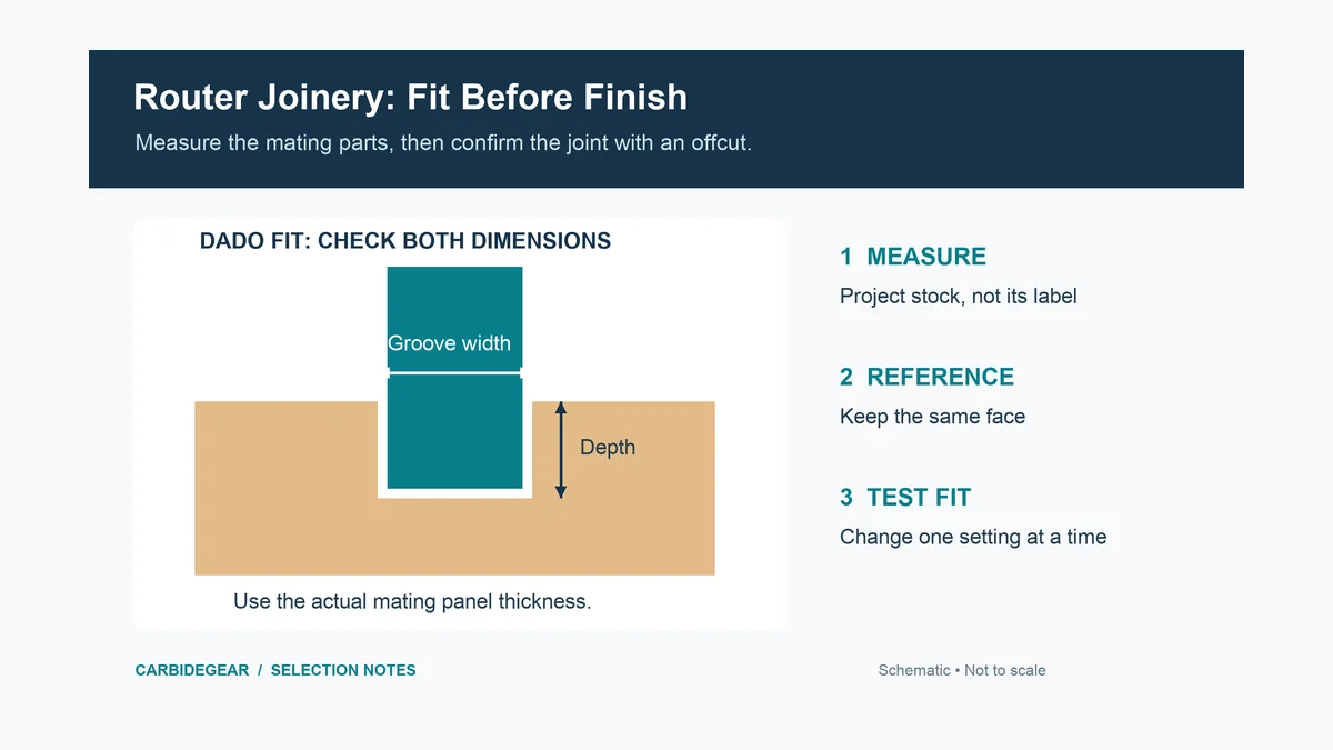
For shelves and cabinet partitions, start with dado router bits matched to the actual panel thickness. The cutter’s nominal size is only the first check: the completed test groove must fit the material you will assemble.
Choosing Router Bits for Woodworking Joints: Start With the Fit
| Joint | What the cutter produces | Dimensions to resolve first |
|---|---|---|
| Dado or groove | Flat-bottomed channel within a face | Channel width, depth, location, and entry method |
| Rabbet | Open-sided step along an edge | Recess width, recess depth, and remaining shoulder |
| Sliding or jig-cut dovetail | Angled mating surfaces | Cutter angle, cutting diameter, depth, and jig specification |
| Tongue and groove | Projecting tongue and matching channel | Tongue thickness, groove width, depth, and reference-face offset |
| Edge slot or spline joint | Narrow slot in an edge | Cutter thickness, radial reach, arbor, and bearing arrangement |
These joints also have different assembly behavior. A dado can locate a shelf, while a sliding dovetail mechanically captures it along its length. Neither name alone determines how much material can be removed or whether the remaining component is strong enough for the project.
Measure the Stock You Will Actually Use
Measure several points on the mating piece and use offcuts from the same batch for setup. A panel sold under a nominal thickness may differ from that number, and a finishing or sanding step can change the fit further. For veneered panels, do not plan to remove the face veneer just to make an oversize piece fit a groove.
Consider a purely dimensional example: a panel measures 0.710 inch while a nominal 3/4-inch cutter measures 0.750 inch. The difference is 0.040 inch before accounting for runout and the actual cut. Those figures demonstrate why nominal matching can leave a loose fit; they are not a recommended clearance or a description of every plywood sheet.
A smaller cutter with a controlled second pass or an adjustable-width jig can accommodate a measured panel. Keep one fixed reference for the first wall, then adjust the other wall. Moving both boundaries without recording the change makes the final location and width harder to control.
Dados and Grooves: Width, Depth, and Entry
A dado runs across the grain; a groove runs with it. Both may use a straight or suitable spiral cutter to form a flat bottom and two walls. For a through channel, a guide must support the router before entry and after exit. For a stopped channel, check the cutter’s entry capability and how the router will stop at the intended endpoint.
Choose enough cutting length to complete the operation while keeping the supported setup practical. Additional length does not make a shallow joint more accurate. Cutter deflection, router movement, a flexible guide, and accumulated chips can all change the result even when the printed diameter looks correct.
Test the actual groove before moving to the finished panel. The mating piece should seat as intended without forcing the walls apart. A dry fit that depends on hammering can become more difficult after glue is applied. An obviously loose groove cannot be corrected simply by adding more glue.
Set depth from the structure of the joint and the material left underneath it. A generic fraction of board thickness is not a substitute for checking load, fasteners, edge distance, and the full design. Keep the intended final joint depth separate from the depth of each cutting pass.
Rabbets: Recess Width and Recess Depth Are Different
A rabbet is open along an edge. For a cabinet back, the recess width accommodates the panel edge, while the recess depth determines its position relative to the back of the case. Reversing those two dimensions in a sketch produces a different joint.
With a simple bearing-guided rabbeting cutter, nominal radial recess width can be understood as (cutting diameter − bearing diameter) ÷ 2, provided the bearing follows the intended straight reference edge. For illustration, a 1.250-inch cutting diameter and a 0.750-inch bearing give a nominal 0.250-inch radial width. Bit height still controls the other dimension, and the test cut establishes the actual result.
Our rabbeting router bit guide compares cutter-and-bearing arrangements for these open-edge recesses. A bearing set only provides the offsets included in that particular system; it does not give continuous adjustment or authorize mixing arbitrary bearings and hardware.
Check that enough uninterrupted edge remains for the bearing to follow. If a previous operation removes the reference surface, the same bit setting can no longer produce the same guided cut.
Dovetails: Start With the Jig Specification
Dovetail bits vary in included geometry, diameter, cutting length, and shank. A jig can require a particular combination of bit and guide bushing, including a specified projection or setup procedure. Buying a bit with a familiar angle does not establish that it will work with the template.
Compare dovetail router bits for the required jig and joint using the jig’s exact requirements. For a sliding dovetail, the male and female surfaces must also meet at the intended depth. Because the surfaces are angled, changing depth can change the fit as well as the joint’s position.
Use paired, labeled offcuts and change one setting at a time. Record the bit position and reference face once the fit is correct. Follow the jig’s removal sequence: an undercut dovetail cutter cannot simply be lifted through an opening that is narrower than its cutting head.
Tongue and Groove: Reference Both Parts From the Same Face
A tongue must fit the groove in thickness, but that is only one dimension. Its projection must suit the groove depth, the shoulders must close, and the visible faces must align. An apparently loose or stepped joint can result from a height mismatch even when the cutter widths are compatible.
The tongue-and-groove router bit selection is useful when comparing matched cutters and their stock-thickness ranges. Keep any specified shims, bearings, and arbor hardware in their prescribed arrangement. A cutter assembly is not a collection of freely interchangeable parts.
Mark a reference face on every piece and use it consistently against the table or guide as the setup requires. This helps control face alignment when stock thickness varies slightly. The exact setup depends on whether the system uses two cutters, a reversible arrangement, or an adjustable assembly.
For frame-and-panel work, also account for the panel design and expected wood movement. A tongue that fits during a dry assembly does not by itself establish the correct panel allowance or gluing arrangement.
Edge Slots and Splines: Check Reach and Hardware
A slot cutter can make a narrow edge recess for a spline or another insert. Cutter thickness sets one dimension, while cutter diameter, bearing, fence position, and arbor geometry affect reach. The spline must suit the finished slot and the remaining wall thickness on both sides.
Use slot-cutting router bits with the required thickness and reach when selecting the assembly. Check permitted shims, cutter orientation, bearing placement, and the manufacturer’s tightening procedure rather than assembling a stack from unrelated parts.
A Repeatable Test-Fit Routine
- Mark the reference face and the final joint location on two offcuts from the project stock.
- Install the specified cutter and guide system; verify collet fit, insertion, clearances, and the approved operating setup.
- Make the intended joint using the planned pass sequence, then remove chips before checking the fit.
- Compare width, depth, shoulder closure, and face alignment separately. Change one adjustment and retest.
- Label the successful sample and record the settings before machining the project parts.
A sample that fits in one spot but binds in another calls for checking the guide, stock consistency, workholding, and cutting stability. When choosing router bits for woodworking joints, treat the sample as a measurement of the whole setup rather than proof that the printed bit size is the finished joint size.
