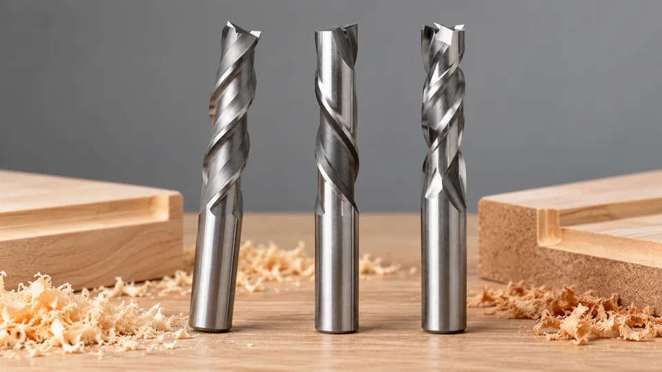
Upcut, downcut, and compression router bits differ primarily in how their spiral flutes move chips and direct cutting forces. An upcut bit carries chips toward the router and generally leaves a cleaner bottom edge. A downcut bit pushes chips into the cut and generally protects the top surface. A compression bit uses opposing flute directions to produce clean top and bottom edges in a through-cut, provided both sections of the flute are correctly positioned in the workpiece.
None of these geometries is universally preferable. Cut type, material construction, workpiece thickness, tool engagement, chip evacuation, and machine setup determine which bit is suitable.
For through-cuts in plywood or veneered panels, our guide to compression router bits for clean panel edges compares the dimensions needed to engage both cutting sections.
Upcut vs Downcut vs Compression at a Glance
| Bit Geometry | Chip Direction | Typical Edge Result | Common Uses | Primary Limitation |
|---|---|---|---|---|
| Upcut | Upward, toward the router or spindle | Cleaner bottom edge, greater risk of top-edge tearout | Mortises, pockets, slots, drilling-style entries, and cuts requiring strong chip evacuation | Can lift fibers, veneer, or laminate at the top surface |
| Downcut | Downward, into the cut | Cleaner top edge, greater risk of roughness or breakout at the bottom | Shallow grooves, top-surface engraving, and cuts in veneered or laminated panels | Traps chips more readily and can increase heat |
| Compression | Toward the interior of the workpiece from both faces | Clean top and bottom edges when properly engaged | Through-cutting plywood, veneered sheet goods, and double-faced panels | Requires correct axial engagement and is often poorly suited to shallow cuts |
How Spiral Direction Affects a Router Cut
A spiral router bit has helical cutting edges wrapped around its body. As the bit rotates, the helix influences the direction in which chips travel along the flutes. It also creates an axial force that can pull the bit or workpiece in one direction.
The terms upcut and downcut describe chip movement relative to the workpiece and router. They do not describe feed direction around the workpiece. Conventional and climb cutting are separate concepts based on the relationship between cutter rotation and travel direction.
Spiral direction affects four practical aspects of routing:
- Edge quality: Fibers or surface layers may be supported or lifted according to the direction of cutting force.
- Chip evacuation: Chips can be extracted from the cut or pushed farther into it.
- Heat: Recirculating or compacted chips can increase friction and heat.
- Axial force: The helix can pull upward or press downward, affecting workholding and tool retention.
Upcut Router Bits
An upcut spiral moves chips upward through the flutes. On a CNC router, that means toward the spindle. With a handheld router used above the workpiece, chips move toward the router base.
This geometry usually provides the strongest chip evacuation of the three types. It is useful for deep slots, pockets, and mortises because chips have a direct path out of the cavity. Effective evacuation reduces the chance of chips being cut repeatedly inside the slot.
Surface Quality and Cutting Forces
The upward shearing action tends to lift wood fibers at the top face. Plywood veneer, melamine, and brittle laminate can chip along that edge, particularly if the surface layer lacks support. The same cutting action directs fibers toward the tool at the bottom of a through-cut, so the lower edge is commonly cleaner.
An upcut helix can also pull the workpiece upward. Secure clamping or vacuum hold-down is therefore necessary. The bit must be correctly seated and clamped in a compatible collet because axial cutting force can aggravate an inadequate toolholding setup.
Where Upcut Geometry Is Useful
- Deep pockets and enclosed slots where chips need a clear exit path
- Mortises and similar blind cavities
- Through-cuts where bottom-edge quality matters more than the top edge
- Operations where chip accumulation is causing heat or poor cutting
- Workpieces whose top surface will be trimmed, covered, or otherwise finished later
An upcut bit may still produce acceptable top edges in solid wood, but results depend on grain direction, edge support, cutting conditions, sharpness, and the specific spiral geometry. The term “upcut” alone does not establish a guaranteed finish.
Where chip evacuation from pockets is the priority, the upcut spiral router bit comparison covers shank and cutting-length choices.
Downcut Router Bits
A downcut spiral drives chips toward the bottom of the cut. Its cutting action presses the top surface inward instead of lifting it. This often produces a cleaner upper edge in veneered plywood, laminated panels, and solid wood that is prone to surface splintering.
Downward force can help keep a sheet seated against the spoilboard or work surface, but it does not replace clamps or a properly functioning vacuum table.
Chip Clearance Is the Main Constraint
Because chips are pushed into the slot or pocket, a downcut bit has less effective chip evacuation in deep, enclosed cuts. Chips can become compacted beneath the cutter. That can increase friction, cause burning in wood, soften some plastics, or degrade the cut.
Downcut geometry is therefore commonly associated with shallow work where chips have room to escape laterally or where top-surface quality has priority. Repeated passes may be appropriate in some operations, but pass depth and cutting parameters must follow the bit manufacturer’s guidance and the capabilities of the router or CNC machine.
Where Downcut Geometry Is Useful
- Shallow dados and grooves requiring a clean top edge
- Engraving or pocketing near a finished face
- Veneered panels and laminated sheet goods where top-face chipping is a concern
- Parts that will retain the upper face while the lower edge is hidden or trimmed
- Thin sheet material that is securely supported from below
A downcut bit can leave a rougher lower edge during a through-cut. It may also push chips against the spoilboard, so a clean top face can be accompanied by less satisfactory chip clearance below.
For top-surface edges, compare downcut spiral router bits while allowing enough room to clear chips.
Compression Router Bits
A compression bit combines an upcut section near the tip with a downcut section above it. During a correctly positioned through-cut, the lower flutes direct cutting action upward while the upper flutes direct it downward. The opposing directions press the surface layers toward the interior of the panel.
This geometry is especially useful for plywood, veneered boards, and panels with finished material on both faces. It can reduce chipping on the top and bottom edges during profile cutting.
Why Engagement Depth Matters
A compression bit produces its intended two-sided result only when the transition between the upcut and downcut sections lies inside the workpiece. The top face must be cut by the downcut portion, while the bottom face must be cut by the upcut portion.
If a shallow pass engages only the upcut tip, the bit behaves as an upcut cutter at the top surface and may lift the veneer. If the workpiece or cutting setup fails to place both flute sections correctly, the expected compression effect will not occur.
The length of the upcut section varies among compression-bit designs. The correct entry and pass strategy must therefore be based on the actual bit drawing or manufacturer specifications rather than a generic depth rule.
Standard and Short-Upcut Designs
Compression bits are available with different lengths in their lower upcut sections. Designs with a shorter upcut portion are sometimes used where the first pass must place the downcut flutes into the top surface sooner. Such tools still require enough engagement for their geometry and cutting edges to work as intended.
A short upcut section does not remove the need to verify flute length, workpiece thickness, entry method, and machine capability. It can also leave less axial length for evacuating chips from the lower part of the cut.
Where Compression Geometry Is Useful
- Through-cutting double-sided laminated panels
- Profiling plywood where both face veneers remain visible
- Cutting cabinet components from veneered sheet goods
- Nested CNC routing where finished top and bottom edges are required
Compression geometry is less suitable for many shallow pockets and dados because the tool may never engage both spiral directions. It also does not guarantee a clean edge if the bit is dull, the panel is unsupported, the workpiece moves, or the cutting conditions are unsuitable.
Matching the Bit to the Operation
Through-Cutting Plywood and Veneered Panels
A compression bit is often appropriate where both faces must remain clean. The bit’s transition point must sit within the panel during the finishing cut. Entry strategy deserves attention because an initial shallow pass with only the upcut section can damage the upper veneer.
If one face is hidden, an upcut or downcut bit may be simpler. Select the spiral direction that protects the visible face while accounting for chip removal.
Cutting Pockets and Mortises
Upcut geometry is generally useful for deeper enclosed cavities because it lifts chips out. A downcut bit may protect the pocket rim, but chip packing becomes more likely as the cut deepens.
Compression bits usually provide little benefit in a blind pocket unless the operation engages both flute directions in a useful way. Their geometry is primarily associated with through-cuts in layered panels.
For template-guided inlay work, compare router inlay kits with cutting and guide hardware after deciding which spiral direction suits the surface.
Shallow Dados and Surface Grooves
A downcut bit can leave a crisp top edge in plywood or veneered board. Since the cut is shallow, chips may have a shorter path out of the groove. Chip buildup still requires monitoring, especially in resinous wood or materials that soften with heat.
Routing Solid Wood
Wood species, grain direction, cut orientation, and edge support can matter as much as spiral direction. Downcut geometry can protect an exposed upper face, while upcut geometry can clear chips efficiently from deeper cuts. Compression bits offer their clearest benefit when both faces need protection during a through-cut.
Routing MDF
MDF does not have face veneer grain like plywood, but it creates fine dust and can generate considerable heat if dust is recut. Upcut geometry supports evacuation from deep slots. Compression geometry can help preserve both edges of coated or laminated MDF panels, provided the opposing flute sections are correctly engaged.
Routing Plastics
Plastic cannot be treated as a single material category. Some plastics form long chips, some are brittle, and others soften readily from heat. Flute polish, cutting-edge geometry, flute count, chip load, and cooling strategy can be as influential as spiral direction. Tool guidance for the specific plastic should take precedence over woodworking assumptions.
For CNC plastic work, use CNC router bits for compatible plastics to match O-flute geometry, shank size, and cutting reach.
Bit Material, Dimensions, and Machine Compatibility
Spiral router bits are commonly available as solid carbide tools, though router-bit construction varies. A solid carbide bit has a carbide cutting body and is distinct from a carbide-tipped bit with cutting edges brazed to a separate body. Spiral direction does not identify the material or construction by itself.
Before mounting any router bit, verify:
- Shank diameter: It must match the collet size approved by the router or spindle manufacturer.
- Cutting diameter: This determines the slot width and affects the cutting load. It is separate from shank diameter.
- Cutting-edge length: The cutting portion must cover the required operation without placing a noncutting section against the workpiece.
- Compression transition location: For a compression bit, confirm where the upcut section changes to downcut.
- Maximum permitted speed: Follow the tool and machine manufacturers’ limits.
- Available clearance: Check fixtures, spoilboards, clamps, and machine travel before cutting.
Never force a shank into an incompatible collet or substitute improvised sleeves. A nominal bit description does not establish compatibility with a particular router, spindle, or toolholder.
Common Selection Errors
- Expecting a compression bit to improve a shallow groove: If only one flute direction enters the material, the bit cannot compress both faces.
- Ignoring the upcut length: A first pass that leaves the transition below the top face can still lift the upper veneer.
- Using a downcut bit in a deep enclosed slot without managing chips: Compacted chips can raise heat and cutting load.
- Assuming downward force provides adequate workholding: Cutting forces can shift or lift material in several directions. Mechanical clamps or a suitable vacuum system remain necessary.
- Confusing spiral direction with routing direction: Upcut and downcut describe axial chip flow. Climb and conventional cutting describe the relationship between rotation and feed travel.
- Selecting by finish alone: A clean upper edge is of limited value if chips cannot leave the cut or the lower face breaks out.
Safe Setup and Use
Inspect the cutting edges and shank before use. Do not run a bit that is chipped, cracked, bent, or contaminated where the collet grips it. Clean and inspect the collet according to the equipment manufacturer’s instructions, then clamp the bit with adequate shank engagement while keeping the flutes out of the collet.
Secure the workpiece, confirm toolpath clearance, and use the router’s guards and dust-control provisions. Eye and hearing protection are appropriate for routing, while respiratory protection and dust collection should reflect the material being cut. Some engineered wood products and composites produce hazardous dust, so their safety information also matters.
Feed rate, spindle speed, pass depth, and entry method depend on the bit diameter and geometry, workpiece material, machine rigidity, toolholder, and manufacturer recommendations. Visible burning, melting, severe vibration, unusual noise, or poor chip evacuation are reasons to stop the machine safely and inspect the setup rather than continuing the cut.
Practical Selection Guide
- Use an upcut bit where chip evacuation and bottom-edge quality have priority.
- Use a downcut bit where the exposed top face needs protection and the cut allows chips to escape adequately.
- Use a compression bit for through-cuts requiring clean top and bottom faces, after verifying that both flute directions will engage correctly.
The comparison between upcut vs downcut vs compression router bits is ultimately a comparison of chip flow, edge support, and axial engagement. Matching those characteristics to the actual cut produces a more reliable result than treating any spiral direction as the default for every material.
