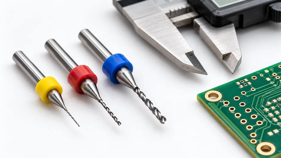
PCB drill bit sizes identify the nominal cutting diameter, usually in millimeters or inches. That dimension must be kept separate from the finished hole diameter, the pad diameter, and the bit’s shank diameter. A 0.80 mm drill with a 3.175 mm shank cuts a nominal 0.80 mm hole while fitting a machine or collet that accepts a 3.175 mm shank.
For a plated-through hole, the finished opening is generally smaller than the drilled opening because copper is deposited on the hole wall. The PCB fabricator selects an appropriate production drill diameter from the finished-hole requirement, plating process, and applicable tolerances. For a non-plated hole, the nominal drill and finished dimensions are more closely related, although drill runout, material behavior, tool wear, and fabrication tolerances can still create a difference.
For actual tool options once the production drill diameter is confirmed, see PCB drill bits in the required diameter, checking the shank separately.
PCB Drill Size Reference Chart
The following table converts example metric diameters to inches and mils. A mil is one-thousandth of an inch. These entries provide dimensional references rather than a list of sizes stocked by every drill manufacturer or supported by every PCB fabricator.
| Nominal Diameter (mm) | Diameter (inches) | Diameter (mils) |
|---|---|---|
| 0.15 | 0.0059 | 5.9 |
| 0.20 | 0.0079 | 7.9 |
| 0.25 | 0.0098 | 9.8 |
| 0.30 | 0.0118 | 11.8 |
| 0.35 | 0.0138 | 13.8 |
| 0.40 | 0.0157 | 15.7 |
| 0.45 | 0.0177 | 17.7 |
| 0.50 | 0.0197 | 19.7 |
| 0.60 | 0.0236 | 23.6 |
| 0.70 | 0.0276 | 27.6 |
| 0.80 | 0.0315 | 31.5 |
| 0.90 | 0.0354 | 35.4 |
| 1.00 | 0.0394 | 39.4 |
| 1.20 | 0.0472 | 47.2 |
| 1.50 | 0.0591 | 59.1 |
| 2.00 | 0.0787 | 78.7 |
| 2.50 | 0.0984 | 98.4 |
| 3.00 | 0.1181 | 118.1 |
| 3.175 | 0.1250 | 125.0 |
Conversions can help identify close metric and inch dimensions, but a converted value does not make two drills identical. For example, 0.80 mm equals approximately 0.0315 inch. A 1/32-inch drill is 0.03125 inch, or 0.79375 mm. The difference is small, yet it may matter for a tightly controlled plated hole or component lead.
Nominal Drill Size Versus Finished Hole Size
PCB drawings and fabrication data can refer to dimensions at different production stages. The relevant terms are:
- Nominal drill diameter: The stated cutting diameter of the drill or the drill callout in manufacturing data.
- Drilled hole: The opening produced before subsequent hole-wall processing and plating.
- Finished hole diameter: The final usable opening after all fabrication steps are complete.
- Pad diameter: The diameter of the copper land surrounding the hole. It is separate from the hole dimension.
- Shank diameter: The portion held by the collet or chuck. It does not identify the hole that the cutting end produces.
Plated-Through Holes
A plated-through hole has conductive material deposited on its wall to connect copper layers or form an electrical connection to a component lead. This buildup reduces the opening from its pre-plating condition. Additional production variables include drill wear, drill-position tolerance, hole preparation, plating control, and measurement method.
There is no reliable universal value that should be added to every desired finished hole. Fabricators use different equipment, process controls, capability limits, and tolerance structures. A designer should specify the required finished hole and tolerance clearly, then follow the selected fabricator’s rules for how that requirement is represented in the design files.
Non-Plated Holes
Non-plated through-holes are commonly used for mechanical mounting, alignment, tooling, or hardware clearance. Since no conductive hole-wall plating reduces the opening, the production drill may be closer to the specified finished size. It still should not be assumed that the actual hole will exactly equal the nominal bit diameter.
A drilled hole can differ from the marked bit size through spindle runout, tool deflection, laminate breakout, tool wear, and normal process variation. Mechanical features requiring a close fit need a stated finished dimension and tolerance rather than an unlabeled drill callout.
How to Determine the Required Hole Diameter
-
Identify the hole’s function.
Classify it as a plated component hole, via, non-plated mounting hole, slot, tooling feature, or another mechanical opening. Each has different electrical and dimensional requirements.
-
Find the component or hardware envelope.
Use the component manufacturer’s drawing rather than measuring a single sample whenever reliable documentation is available. Account for lead width, thickness, shape, tolerances, coatings, and forming.
-
Allow suitable assembly clearance.
The finished hole must accept the largest permitted lead or hardware dimension while supporting the intended assembly process. Hand insertion, automated insertion, soldering, press-fit connections, and mechanical fasteners have different clearance requirements.
-
Specify whether the dimension is finished or drilled.
Ambiguous fabrication notes can produce incorrect results. Confirm how the PCB fabricator interprets hole sizes in the submitted NC drill files, fabrication drawing, and order options.
-
Check the fabricator’s capability limits.
Minimum hole diameter, available drill increments, board thickness, hole aspect ratio, plating capability, and tolerance all influence manufacturability.
-
Verify the surrounding pad and clearances.
Changing a hole size changes the remaining annular ring and may affect internal-layer clearances. Review the complete pad stack after modifying the drill diameter.
Square and Rectangular Leads
A round hole must clear the largest cross-sectional dimension of a non-round lead. For a square pin with side length s, the diagonal is:
Diagonal = s × √2
A round finished hole smaller than that diagonal cannot freely accept a perfectly square pin of the stated side length. Pin tolerances, corner shape, plating, insertion clearance, and lead alignment must also be addressed. Using the square pin’s side dimension alone can produce an undersized hole.
Size Selection by PCB Feature
| Feature | Dimension That Drives Selection | Important Constraint |
|---|---|---|
| Plated component hole | Maximum lead envelope plus assembly clearance | Finished diameter after plating |
| Via | Electrical and routing requirements | Fabricator minimums, board thickness, and pad stack |
| Press-fit hole | Connector manufacturer’s finished-hole specification | Tight tolerance and controlled plating |
| Non-plated mounting hole | Fastener, boss, or locating-pin dimensions | Required mechanical clearance or fit |
| Plated slot | Lead width, lead length, and insertion clearance | Routing or slotting capability and end radius |
| Tooling hole | Fixture or process requirement | Position and diameter tolerance |
Component family names alone do not define a drill size. Two connectors with the same pin pitch may use different pin cross sections. Likewise, mounting holes for similarly labeled screws can require different diameters according to the desired clearance class, plating status, and hardware specification.
PCB Micro-Drill Construction
PCB micro-drills commonly use cemented tungsten carbide because glass-reinforced PCB laminates are abrasive. Cemented carbide provides high hardness and wear resistance, but it has less tolerance for bending and impact than HSS. Small diameters are particularly vulnerable to breakage from runout, misalignment, poor support, or sideways contact.
“Carbide PCB drill” does not describe every construction detail. Some tools use an integral carbide body, while others may use a composite construction with a carbide working section and a different shank material. The cutting material, joint construction, geometry, and shank specification should be confirmed from the tool documentation.
PCB micro-drills also differ from carbide-tipped masonry drills. A masonry drill typically has a carbide tip attached to a larger steel body and uses geometry intended for mineral materials. It is not a substitute for a precision PCB drill.
The difference between solid-carbide and carbide-tipped drills also helps clarify which tool construction you are buying.
Cutting Diameter and Shank Compatibility
Many PCB drills use a 3.175 mm (1/8-inch) shank across several cutting diameters. This arrangement allows one suitable collet to hold drills that produce different hole sizes. The 1/8-inch shank is common, but it is not universal.
Before mounting a drill, verify:
- The actual shank diameter matches the chuck, collet, or toolholder.
- The holder is rated to grip that shank securely.
- The spindle and holder have sufficiently low runout for the drill diameter.
- The usable cutting length can pass through the board and backing material without excessive projection.
- The equipment manufacturer permits the tool type and intended operation.
A collet size does not determine the cutting diameter. A 3.175 mm shank drill may have a much smaller cutting end, while a 3.175 mm cutting diameter does not automatically mean the shank is also 3.175 mm.
CNC Fabrication Versus Manual PCB Drilling
Production PCB drilling uses rigid, low-runout equipment with controlled positioning, suitable entry and backing materials, and process parameters matched to the drill and laminate. Micro-drills are engineered around those conditions.
Manual drilling introduces greater risks of side loading and misalignment. A handheld power drill generally lacks the control required for very small carbide drills. A rigid drill press or purpose-built PCB drilling spindle provides better alignment, but the machine must still accept the shank correctly and keep the board securely supported.
HSS drills may tolerate flexing better during some low-volume manual work, though they generally wear faster in glass-reinforced laminate. Tool material does not compensate for excessive runout, a loose workpiece, or an incompatible holder.
Why Actual Holes Can Differ From the Marked Size
The engraved or listed diameter is a nominal tool dimension. Actual results can be affected by:
- Spindle and collet runout
- Drill wear or cutting-edge damage
- Tool deflection
- Board-stack movement
- Entry and exit breakout
- Laminate composition
- Hole-wall preparation
- Copper plating thickness and uniformity
- Inspection method and stated tolerance
Replacing one nominal size with a close inch or metric alternative should therefore be based on the allowed finished-hole range, not on conversion proximity alone.
Handling and Drilling Safety
Carbide micro-drills are sharp and brittle. A broken tool can produce small high-speed fragments. Wear appropriate eye protection, secure the board, use machine guards provided by the equipment manufacturer, and keep hands away from the rotating tool.
Fiberglass-reinforced laminate also creates dust that should be controlled with suitable extraction and handling practices. Do not clear debris near a moving spindle. Stop and isolate the machine before changing a bit, inspecting a broken tool, or adjusting the workpiece.
PCB Drill Size Questions
Does a 0.80 mm PCB drill produce a finished 0.80 mm plated hole?
Not necessarily. The bit has a nominal cutting diameter of 0.80 mm, while plating and fabrication variation affect the finished opening. If 0.80 mm is the required finished diameter, the fabricator may use a larger production drill according to its process.
Is 3.175 mm the cutting diameter of a PCB drill?
It can be, but 3.175 mm more frequently appears as the shank diameter on PCB micro-drills. Read the specification carefully to separate cutting diameter from shank diameter.
Can the nearest inch drill replace a metric PCB drill?
Only if the resulting hole remains inside the acceptable dimensional range. Close inch and metric sizes are often different by several thousandths or ten-thousandths of an inch. Plating, lead clearance, and fabrication tolerance determine whether that difference is acceptable.
Should component holes be sized from the pin pitch?
No. Pitch identifies the spacing between pins, not their width, thickness, or diagonal. Hole size should follow the maximum lead envelope, required assembly clearance, plating status, and finished-hole tolerance.
Who selects the production drill for a plated PCB hole?
In commercial fabrication, the designer communicates the required hole information through design data and fabrication requirements. The fabricator then applies its documented process compensation, subject to the agreed capabilities and tolerances. Confirm file conventions and hole definitions before submitting the board.
