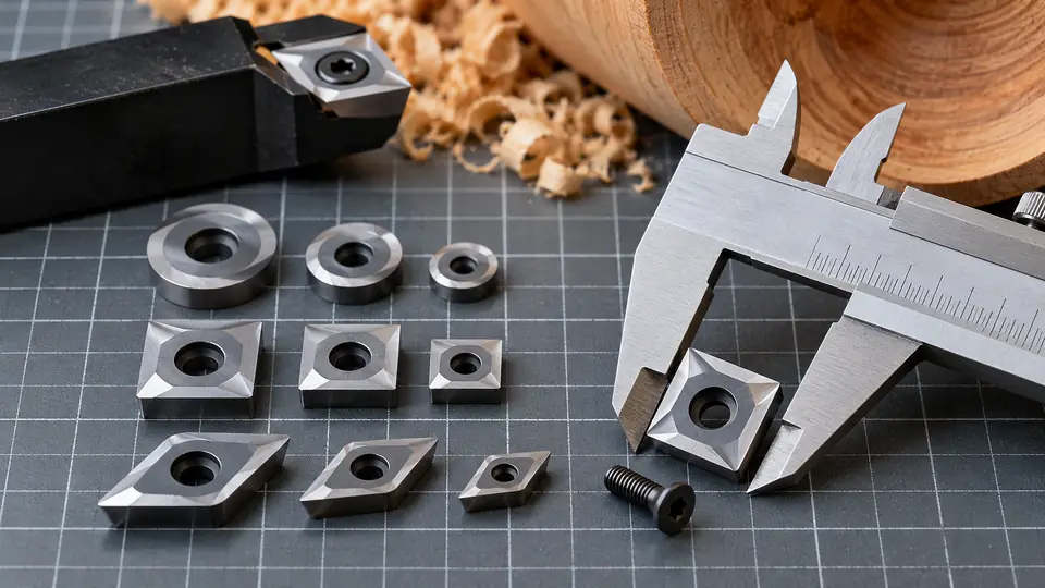
Woodturning carbide inserts are sized by their cutter geometry and physical dimensions, but there is no universal sizing system that guarantees interchangeability. A replacement must match the insert seat, outside dimensions, thickness, mounting-hole shape, screw head, and cutting-edge orientation of the tool. Two cutters advertised as 12 mm square or 16 mm round can still require different holders or screws.
Size labels provide a useful starting point. The safest method is to identify the tool manufacturer’s specified cutter or compare every relevant dimension with the original insert before installation.
After confirming the seat dimensions, use our woodturning replacement inserts guide to match the cutter shape, thickness, and mounting screw.
How Woodturning Carbide Insert Sizes Are Described
Woodturning cutters are commonly identified by shape and a nominal outside measurement. A square insert may be listed by side length, while a round insert is usually listed by diameter. Diamond-shaped cutters may use length and width, an included angle, or a manufacturer-specific name.
| Cutter Shape | Typical Size Description | Other Dimensions That Must Match |
|---|---|---|
| Square | Side length, usually in millimeters | Thickness, corner radius, hole, countersink, edge orientation |
| Round | Outside diameter | Thickness, center hole, countersink, screw fit, seat diameter |
| Diamond or detail | Length and width, sometimes tip angle | Thickness, hole position, countersink, point geometry, seat shape |
| Radiused square | Side length plus corner or edge radius | Thickness, hole geometry, relief, holder-seat profile |
| Special profile | Manufacturer-specific designation | Complete profile, thickness, mounting system, cutting-edge orientation |
Metric labels are widespread. Square cutters may be encountered with nominal side lengths such as 10, 11, 12, 14, or 15 mm, while round cutters are sold in several diameters, including sizes around 8, 10, 12, and 16 mm. These are examples of market labels rather than a standardized progression. A nominal measurement alone does not establish compatibility.
The Dimensions That Determine Compatibility
Outside Length, Width, or Diameter
The insert must sit fully against the tool’s supporting pocket or shelf. An undersized cutter can shift or lack adequate support. An oversized cutter may overhang incorrectly, interfere with the holder, or fail to seat.
Measure a square insert across one side rather than diagonally. Measure a round cutter across its widest point through the center. For a diamond cutter, record the overall length, maximum width, and point angle if that angle can be identified reliably.
Thickness
Insert thickness affects the height and support of the cutting edge. A cutter with the correct outline but the wrong thickness may sit above or below its intended position. It can also prevent the screw head from clamping correctly.
Thickness should be measured away from raised edge features and accumulated debris. Resin beneath an insert can produce a misleading measurement and prevent a replacement from seating flat.
Mounting-Hole Diameter and Shape
A center hole can be cylindrical, tapered, or countersunk. The upper recess may be sized for a flat-head, countersunk, or other manufacturer-specified screw. Hole geometry matters because the screw head often helps center and clamp the cutter.
A screw passing through the hole does not prove that the combination fits. Excess clearance can permit movement, while an incorrect countersink can concentrate clamping force around a small contact area.
Screw Diameter, Thread, and Head Profile
The mounting screw must match the threads in the tool shaft and the recess in the cutter. Similar-looking screws may have different diameters, pitches, head angles, or lengths. Metric and inch threads must not be mixed.
Reuse the screw type specified for the holder. A longer screw can bottom out before clamping the insert, while a shorter one may provide inadequate thread engagement. An oversized or mismatched head can damage the brittle carbide around the mounting hole.
Corner Radius and Cutting Profile
Square cutters may have sharp corners, slightly rounded corners, or a larger radius along the cutting edge. Those profiles behave differently in wood and may require different pockets.
- Sharp or small-radius corners can produce defined shoulders but may engage aggressively if presented poorly.
- Larger-radius square cutters spread the cut across a curved edge and are often used for smoother shaping.
- Round cutters provide a continuously curved perimeter and can usually be rotated to expose a fresh section.
- Diamond cutters have a narrow point suited to detail work, beads, grooves, and confined areas.
A holder intended for one profile should not be assumed to support another simply because the mounting holes align.
Bevel, Relief, and Cutting-Edge Orientation
Many woodturning replacement cutters use a polished top surface and relief beneath the cutting edge. The edge geometry establishes how the cutter meets the wood. Some inserts are flat, while others are dished, cupped, or molded into a specialized profile.
Flipping an insert can place the wrong face toward the workpiece and remove the required clearance. Install it in the orientation specified for the tool.
For resin or acrylic turning, compare negative-rake woodturning cutters only after matching the tool seat and screw.
Square, Round, and Diamond Cutters Serve Different Roles
| Shape | Common Woodturning Use | Compatibility Concern |
|---|---|---|
| Square | General shaping, straight cuts, shoulders, and outside work | Side length, corner radius, and seat support must match |
| Round | Curves, hollowing, smoothing, and blended profiles | Diameter alone does not identify hole or countersink geometry |
| Diamond | Detailing, grooves, beads, and narrow access | Point angle, hole location, and holder profile vary |
| Radiused square | General shaping with a less abrupt corner engagement | Radius must clear the holder and match its intended presentation |
Shape names describe broad geometry rather than a complete specification. “Square,” “round,” and “diamond” do not identify one fixed size or mounting arrangement.
How to Measure a Replacement Cutter
A digital or dial caliper is more useful than a ruler for checking small differences. Remove the cutter only after the lathe has been stopped and disconnected from power according to its manual. Handle the edge carefully because it remains sharp after it stops cutting efficiently.
- Clean the original cutter. Remove dust and resin without altering the edge or seating surfaces.
- Identify its geometry. Record whether it is square, round, diamond-shaped, radiused, cupped, or another profile.
- Measure the outside size. Check square side length, round diameter, or diamond length and width.
- Measure thickness. Take the reading through a flat section of the insert.
- Check the center hole. Record the narrow hole diameter and the diameter of any upper recess.
- Inspect the countersink. Determine whether the recess is straight-sided, tapered, stepped, or otherwise shaped.
- Record the cutting profile. Note corner radii, a dished top, edge relief, and which face points upward.
- Verify the screw separately. Use the holder documentation to identify its thread and specified screw. Do not infer the thread from a rough diameter measurement.
- Compare with the holder specification. Confirm the complete replacement designation where manufacturer information is available.
Measurements taken from a worn or chipped cutter require care. A damaged corner can make a square insert appear smaller, and wear around the hole can hide the original fit.
Why Matching the Nominal Size Is Insufficient
Suppose two inserts are both labeled “12 mm square.” One may be thicker, have a larger center hole, use a different countersink, or have a larger corner radius. It may sit on the holder, yet the screw head might contact only the rim of the recess or the cutter might rock against the seat.
The same problem occurs with round cutters. Diameter describes the outer circle, but it says nothing about thickness, hole geometry, edge relief, or the shape of the supporting pocket. Visual similarity cannot establish interchangeability.
Tolerances also matter. A nominal 12 mm label does not promise that every supplier uses the same drawing, dimensional tolerance, or carbide blank. Match the specified cutter rather than treating the label as a universal standard.
Woodturning Cutters Versus Industrial Turning Inserts
Woodturning replacement cutters are often confused with indexable inserts made for metal lathes. Both may use cemented carbide and a center screw, but they belong to different tooling systems.
Industrial turning inserts may carry standardized designations such as CCMT, DCMT, TNMG, or WNMG. Those codes communicate defined geometric characteristics within the applicable designation system. Additional characters and manufacturer codes can identify size, thickness, nose radius, chipbreaker, grade, or coating.
Many woodturning cutters use simpler retail descriptions such as “12 mm square” or a proprietary cutter name. Their seats and screws are commonly specific to a woodturning tool family. An industrial insert that resembles a woodturning cutter should not be fitted unless the holder manufacturer explicitly identifies it as compatible.
Replacing and Indexing an Insert Safely
Carbide is wear resistant but comparatively brittle. Poor support, debris under the insert, or excessive screw force can chip or crack it.
- Disconnect the lathe from power before changing or rotating a cutter.
- Clean the pocket and underside of the insert so the cutter rests flat.
- Inspect the screw, threads, holder seat, and insert for damage.
- Position the correct face and edge according to the tool instructions.
- Use the specified screw and tightening method. Avoid adding leverage with an oversized wrench.
- Replace cracked, chipped, or loose inserts rather than continuing to use them.
- Rotate an indexable cutter only through positions supported by its shape and holder.
Round cutters can often be rotated by a small amount to expose fresh edge. Square cutters are commonly indexed to another corner. The permitted indexing method still depends on the holder and cutter design.
A Practical Compatibility Checklist
Before installing a replacement, confirm all of the following:
- The cutter shape matches the holder pocket.
- The outside length, width, or diameter matches.
- The insert thickness is correct.
- The corner radius or edge profile is the same.
- The center-hole diameter matches.
- The countersink or recess fits the specified screw head.
- The screw thread, length, and head geometry are correct.
- The cutting face is oriented correctly.
- The insert sits flat without rocking or unsupported overhang.
- The replacement is explicitly specified for the tool, where documentation is available.
If any measurement or mounting detail differs, treat the insert as incompatible until reliable tool documentation confirms otherwise. For carbide inserts for woodturning, size is a group of dimensions and geometric features rather than a single number.
