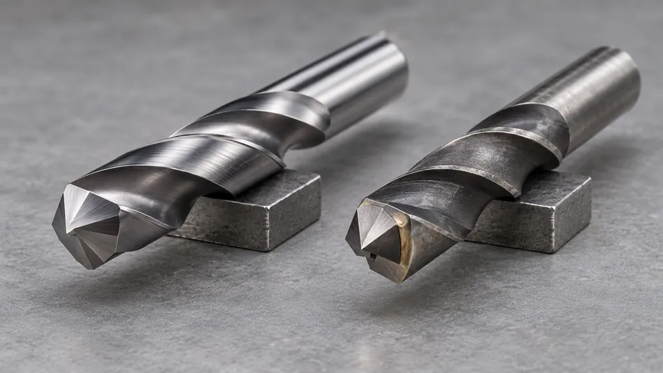
Solid carbide drill bits carry carbide through the cutting section of the tool, while carbide-tipped drill bits use a carbide cutting element attached to a body made from another material, commonly steel. That construction difference affects rigidity, wear behavior, breakage risk, cost, reconditioning, and the equipment required to use the drill successfully.
The terms still need application context. A carbide-tipped masonry bit and a solid carbide metalworking drill are built for different cutting actions. They should not be treated as interchangeable merely because both contain cemented carbide.
When the job is concrete, our guide to carbide-tipped bits for concrete separates the options by hole size, hammer compatibility, and working length.
Solid Carbide and Carbide-Tipped Construction
Solid Carbide Drill Bits
A solid carbide drill is manufactured with carbide throughout its cutting section rather than having a small carbide plate brazed onto a steel drill body. In many conventional designs, the carbide extends through the fluted body and shank. Some specialized drills combine a solid carbide cutting section with another shank construction, so the manufacturer’s specification remains the reliable way to confirm exactly what “solid carbide” means for a particular tool.
The material is generally cemented carbide. Hard carbide particles, commonly tungsten carbide, are held together by a metallic binder. Its exact wear resistance, toughness, and fracture behavior vary with grade, grain structure, binder content, geometry, coating, and manufacturing process.
Solid carbide construction provides a stiff cutting body and allows precise cutting edges, flute forms, margins, and point geometries to be ground into the carbide. These characteristics make it common in CNC drilling, printed circuit board production, and other controlled machining operations.
Carbide-Tipped Drill Bits
A carbide-tipped drill has one or more carbide cutting elements attached to a tougher and less costly body. Brazing is a common attachment method, although construction varies among tool families. The steel body provides the flutes, shank, and much of the drill’s structural support, while the carbide performs the cutting at the point.
The carbide portion may be a relatively simple transverse plate, separate cutting segments, or a more specialized tip. This category includes very different tools:
- Masonry drills commonly use a carbide tip shaped for rotary or rotary-hammer drilling in concrete, brick, or masonry.
- Specialized metalworking drills may use accurately formed carbide cutting elements on a steel body.
- Construction drills for tile, fiber-cement products, and other abrasive materials may have application-specific tip shapes.
The presence of a carbide tip does not establish suitability for steel, concrete, tile, or any other material. Point geometry, flute design, shank interface, and the manufacturer’s stated application provide that information.
Solid Carbide vs Carbide-Tipped Drill Bits at a Glance
| Characteristic | Solid Carbide | Carbide-Tipped |
|---|---|---|
| Construction | Carbide extends through the cutting section, often through the fluted body and shank | Carbide cutting element attached to a steel or other non-carbide body |
| Rigidity | Typically high | Body is generally more flexible than a comparable solid carbide body |
| Wear resistance | Carbide is available throughout the cutting section | Wear-resistant material is concentrated at the tip |
| Impact tolerance | Susceptible to chipping or fracture under vibration, impact, misalignment, or poor clamping | Steel body can tolerate more flex, but the carbide tip and braze joint remain vulnerable |
| Typical equipment | Rigid CNC machines, drill presses, precision spindles, and other controlled setups | Varies widely, from rotary hammers to machine tools, depending on the drill design |
| Initial cost | Usually higher for a comparable size and application | Often lower because less carbide is used, though specialized designs can still be costly |
| Reconditioning | May permit multiple regrinds if sufficient material and suitable equipment are available | Limited by tip dimensions, attachment, wear, and the manufacturer’s reconditioning provisions |
| Common limitation | Needs good alignment, low runout, secure workholding, and adequate machine rigidity | Cutting geometry and service life are constrained by the attached tip |
How the Construction Changes Drilling Performance
Rigidity, Runout, and Hole Control
Carbide is much stiffer than ordinary drill-body steels. A solid carbide drill therefore resists elastic deflection, which can support accurate hole location and stable cutting in a rigid setup. Precision still depends on spindle condition, toolholding, runout, drill geometry, workpiece stability, and proper entry into the material.
That same stiffness leaves little capacity for bending. Misalignment between the drill and workpiece, an unstable fixture, excessive runout, or movement during entry can place damaging loads on the cutting edges. Small-diameter solid carbide drills are especially sensitive because a small cross-section offers little tolerance for lateral force.
A carbide-tipped drill’s steel body can flex more before breaking. This may make the complete tool less prone to snapping under imperfect conditions, but flex can reduce positional control. The carbide tip can still chip, detach, or wear unevenly if the tool is misused.
Wear Resistance and Edge Retention
Both constructions place carbide at the cutting edge, so either can resist abrasive wear better than a comparable uncoated steel edge in a suitable application. Their wear behavior is not identical.
On a solid carbide drill, the point, margins, and flute surfaces can all be formed from carbide. This permits the entire cutting section to benefit from the selected carbide grade. Coatings may be applied to further address wear, friction, or heat in specific workpiece materials.
On a tipped drill, carbide is concentrated where the designer expects the principal cutting action. The steel behind it does not gain carbide’s wear properties. Once the tip has worn beyond its usable geometry, there may be insufficient carbide left for further service.
Heat and Cutting Conditions
Carbide can retain a cutting edge under conditions that would soften many conventional tool steels, but this does not make every carbide drill tolerant of uncontrolled heat. Poor chip evacuation, an unsuitable point, excessive edge wear, or incorrect coolant use can damage either construction.
Some metalworking drills include internal coolant passages, while others depend on external coolant or application-specific dry cutting. Coolant strategy must match the drill design, workpiece, machine, and manufacturer’s guidance. Intermittent or poorly directed coolant can create unfavorable temperature changes in some operations.
Interrupted and Unstable Cutting
Cross holes, uneven entry surfaces, stacked components, and poorly secured workpieces can impose interrupted or lateral loads. Solid carbide’s lower tolerance for deflection raises the risk of edge chipping or complete fracture in these conditions.
A tipped drill may gain some resilience from its steel body, but its suitability still depends on tip geometry and attachment. A masonry bit built for impact is a special case. Its carbide tip, body, and shank are configured for a drilling mechanism that differs substantially from metal-cutting twist drilling.
Applications for Solid Carbide Drills
Solid carbide drills are most useful where their stiffness, wear resistance, and accurately ground geometry can be supported by the equipment. Typical applications include:
- Production drilling on rigid CNC machinery
- Precision holes in metallic workpieces using an application-specific drill
- Drilling abrasive composite materials with suitable geometry
- Micro-drilling printed circuit boards and other thin, abrasive laminates
- Operations requiring consistent geometry across repeated holes
PCB micro-drills illustrate both the advantage and limitation of solid carbide. Their rigid cutting sections can produce very small holes in abrasive laminates, but minor spindle runout, handling damage, or board movement can break them. They are intended for appropriate high-precision equipment rather than casual use in an ordinary hand drill.
Solid carbide is also used for difficult metalworking applications, but workpiece hardness alone does not determine suitability. Material condition, drill grade, coating, point geometry, hole depth, chip evacuation, holder quality, and machine rigidity all affect the result.
Applications for Carbide-Tipped Drills
Carbide-tipped construction is useful where carbide is needed at the cutting edge but a complete carbide body would be impractical, fragile, or unnecessarily expensive.
Masonry and Concrete
Many familiar carbide-tipped drills are masonry tools. Their broad carbide cutting plates crush and remove mineral material rather than cutting metal with the geometry of a conventional metalworking drill. Rotary-hammer versions may use SDS-Plus, SDS-Max, or another specified shank system, while standard rotary masonry drills use different shanks and operating methods.
A masonry drill should not be selected for steel because it has a carbide tip. Its point and flute system are intended for masonry-related workpieces and drilling actions.
For a hammer with an SDS-Max chuck, the SDS-Max concrete drill bit comparison groups options by diameter, reach, and cutting method.
Large or Specialized Industrial Drilling
Using carbide only at the cutting point can reduce material cost, particularly as tool diameter increases. A steel body can also support specialized constructions that would be expensive or difficult to produce entirely from carbide.
Industrial carbide-tipped metal drills differ significantly from general-purpose masonry drills. Their cutting geometry, margins, coolant delivery, and recommended operating conditions are tailored to metal removal. The stated workpiece range should be checked before use.
For ring-cutting on a compatible magnetic drill, compare carbide-tipped annular cutters by Weldon shank and rated cutting depth.
Abrasive Building Materials
Some tipped drills are made for tile, brick, fiber-cement materials, or related products. These materials do not share one universal drilling method. Glazed tile, porcelain, concrete, and brick can require different tip geometries, machine actions, and cooling practices. A tool labeled simply “carbide tipped” provides too little information for selection.
For a tile surface that permits carbide tooling, compare carbide-tipped bits for tile and check the drill mode and surface compatibility.
Which Construction Fits the Setup?
Use a solid carbide drill as a candidate where the machine has a rigid spindle, an accurate holder, low runout, secure workholding, and control appropriate to the drill. It is especially relevant where hole consistency, edge retention, and production performance justify the higher tool cost.
Use a carbide-tipped drill as a candidate where an application-specific tip provides the required cutting action and a steel body offers practical cost or toughness advantages. Masonry drilling is the clearest example, but specialized metalworking and construction-material drills also use this design.
A hand drill generally does not provide the alignment and rigidity expected by a precision solid carbide metalworking drill. Operator movement can apply lateral force and fracture the tool. Some carbide-tipped drills are intended for handheld equipment, but only in the applications and operating modes specified for that drill.
Specifications That Matter More Than the Carbide Label
Construction is one selection factor. The following details often determine whether a drill will function correctly:
- Intended workpiece: Steel, cast iron, nonferrous metal, concrete, brick, tile, composites, and PCB laminates require different cutting geometries.
- Drill diameter: Diameter affects rigidity, required torque, chip formation, and holder compatibility.
- Point geometry: Point angle, edge preparation, web design, and centering features influence entry and cutting behavior.
- Flute design: Flute form and length affect chip transport and usable drilling depth.
- Shank type and diameter: The shank must match the chuck, collet, or spindle interface without improvised adapters.
- Coating: A coating changes surface behavior but does not convert a steel drill into solid carbide.
- Coolant provision: Through-coolant and external-coolant designs require different machine capabilities.
- Operating mode: Rotary-only, percussion, and rotary-hammer drilling are distinct modes. The tool and machine must support the selected mode.
For a larger opening in compatible stainless sheet, the guide to carbide hole saws for stainless-steel sheet separates cutter diameter from permitted sheet thickness and drill fit.
Cost, Regrinding, and Service Life
Solid carbide drills usually cost more initially because they contain more carbide and often require precise grinding. Their economic value is tied to usable performance in a compatible production process, rather than purchase price alone.
Some solid carbide drills can be professionally reground and recoated. Reconditioning changes the point and can affect drill length, diameter near the point, edge preparation, coating coverage, and coolant-hole geometry. The drill manufacturer or a qualified regrinding service should determine whether a particular tool is suitable for reconditioning.
Carbide-tipped drills may also be resharpened, but the available carbide is limited. Grinding must preserve the tip geometry and avoid damaging the attachment. Small, inexpensive masonry drills are often replaced after wear, while larger industrial tools may justify specialist service.
Service life cannot be predicted from construction alone. Edge damage, abrasive wear, tip detachment, flute erosion, thermal damage, and body deformation are different failure modes. Workpiece material and setup quality may outweigh the nominal distinction between solid and tipped construction.
Handling and Safety
Inspect the drill before installation. Do not use a tool with a chipped edge, cracked carbide, damaged shank, loose tip, obstructed coolant passage, or visible distortion. Clean the shank and holder so debris does not create runout or reduce clamping security.
Secure the workpiece, use the machine’s guards, and wear eye protection appropriate to the operation. Carbide can fracture into sharp fragments. Keep hands away from rotating tooling and chips, and stop the machine before inspecting or clearing the work area.
Confirm that the drill’s shank, diameter, length, operating mode, and permitted speed range match the machine. For rotary-hammer work, use the exact shank interface and tool type specified by the equipment manufacturer. A carbide cutting edge does not compensate for an incompatible holder or unsupported drilling method.
The Practical Distinction
Solid carbide drills emphasize rigidity, precise geometry, and wear-resistant construction throughout the cutting section. They perform best in controlled setups capable of protecting a hard but fracture-sensitive tool.
Carbide-tipped drills place carbide where cutting occurs while retaining a steel body for cost, flexibility, or application-specific construction. Their capabilities vary widely, from impact-oriented masonry bits to specialized industrial metal drills.
The correct comparison therefore starts with construction and ends with application. Identify the workpiece, drilling action, machine interface, point geometry, and required hole before deciding which carbide design is appropriate.
