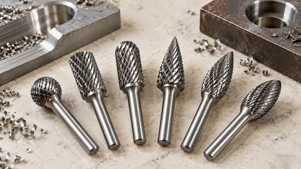
Carbide burr shapes determine where the cutting edges contact the workpiece, which surfaces the tool can reach, and the type of contour it tends to produce. Cylindrical burrs suit flat surfaces, ball burrs follow concave profiles, tree and flame shapes reach curved or confined areas, and cone forms create bevels or open tapered features. The shape should match the required surface and access angle rather than the workpiece material alone.
The cutting profile is separate from the tooth pattern. A ball-shaped burr, for example, may be available with single-cut, double-cut, or nonferrous-oriented cutting geometry. Shape controls contact and access. Tooth pattern influences chip formation, cutting action, and the resulting surface.
See our selection of carbide burr sets with several head shapes when the job calls for a mix of cylindrical, ball, and tapered profiles.
Carbide Burr Shape Reference
Manufacturers may use different names for similar profiles. Letter designations are also common, but a code should be confirmed against the specific manufacturer’s catalog before ordering. The following table focuses on physical geometry and typical functions rather than treating any code as universal.
| Shape | Contact Geometry | Typical Uses | Main Limitation |
|---|---|---|---|
| Cylindrical, plain end | Straight sides with a flat, usually noncutting end | Leveling surfaces, enlarging straight slots, edge work | Cannot efficiently cut the floor of a recess unless the end has cutting teeth |
| Cylindrical, end cut | Straight sides and cutting edges across the end | Flat-bottom recesses, inside corners, surface and face cutting | Sharp internal corners can concentrate stress in the workpiece |
| Ball-nose cylinder | Straight body ending in a rounded nose | Blending flat surfaces into fillets, contouring, smoothing rounded transitions | Does not produce a sharp-bottomed corner |
| Ball | Spherical cutting surface | Concave contours, radius work, porting, cavity shaping | Small contact areas can dig into the workpiece if pressure is uneven |
| Oval | Rounded, elongated profile | Curved surfaces, broad radii, edge blending, deburring irregular profiles | Poor fit for flat-bottom features or sharp corners |
| Tree, radius end | Tapered body with a rounded tip | Rounded slots, fillets, curved recesses, mold and die contours | The taper can unintentionally widen an opening |
| Tree, pointed end | Tapered body ending in a narrow point | Acute profiles, narrow grooves, detailed contour work | The point is less robust and has limited cutting speed at its center |
| Flame | Long, flowing curve with a narrow rounded tip | Concave surfaces, elongated contours, narrow openings, gradual blending | Less suitable for producing straight walls |
| Cone | Tapered sides with a pointed or truncated end | Beveling, opening holes, rough chamfering, V-shaped grooves | The included angle must match the intended feature |
| Tapered ball nose | Tapered body with a rounded end | Drafted walls, tapered recesses, curved transitions in confined spaces | Cannot create a square corner at the bottom |
| Inverted cone | Cutting diameter increases behind a narrower end | Back chamfers, undercuts, rear-edge deburring, dovetail-like recesses | Can become trapped in the feature if access and withdrawal are not planned |
How Each Shape Behaves
Cylindrical Burrs
A cylindrical burr places a relatively long section of its side against the workpiece. This broad contact can help level high spots and straighten an edge, but it also increases cutting load compared with a small point of contact. Stable tool control and rigid workholding become more significant as engagement increases.
Plain-end and end-cut cylinders serve different purposes. A plain-end cylinder primarily cuts with its sides. An end-cut version can work on the floor of a recess and approach an internal corner. Catalog illustrations can look nearly identical, so the end-cutting specification should be checked directly.
Ball and Ball-Nose Burrs
A ball burr is useful where the surface curves in several directions. Its profile can enlarge a concave cavity, blend intersecting contours, or create a radius. Tilting the tool changes the effective contact area, making control highly dependent on hand position or programmed toolpath.
A ball-nose cylinder combines straight sides with a rounded end. It is often easier to use for blending a wall into a floor because the radius avoids the sharp transition produced by a square-ended cutter. The resulting fillet size depends on the burr geometry and how deeply the tool engages.
Oval, Tree, and Flame Burrs
Oval burrs provide a continuous curve without an abrupt cylindrical section. They fit broad concave shapes and irregular edges, especially where a ball would contact too small an area.
Tree burrs narrow toward the tip, allowing access to slots and recessed contours. A radius-end tree leaves a rounded transition, while a pointed tree reaches farther into acute features. The tapered profile removes material from the sides of an opening as it advances, so depth and width cannot be treated independently.
Flame burrs have a longer curved transition than most oval or tree forms. This geometry suits gradual contouring and blending inside elongated recesses. Its curved sides make it poorly suited to features that require a controlled straight wall.
Cone and Tapered Burrs
Cone burrs are used for rough bevels, tapered openings, and V-shaped features. They may be identified by their included angle, tip style, or overall profile. Two cone burrs that appear similar can produce different wall angles, so visual comparison is insufficient for angle-sensitive work.
A carbide burr can rough a chamfer, but it does not automatically provide the dimensional control or surface geometry of a dedicated chamfering or countersinking tool. Precision holes and fastener seats normally require tooling made for that specific feature.
Inverted Cone Burrs
An inverted cone reaches behind an edge or creates an undercut. This capability also introduces a withdrawal constraint. The widest cutting section must be able to exit the feature without striking an obstruction or locking behind the workpiece geometry.
Side loading should remain controlled. An inverted cone is not a pry tool, and levering it inside an undercut can fracture the carbide head or bend the shank.
Shape and Cut Pattern Are Different Specifications
Most carbide rotary burrs use a cemented carbide cutting head, frequently joined to a steel shank. The term carbide burr does not necessarily mean that the full shank and head are one solid piece of carbide.
Cutting-edge pattern must be evaluated alongside shape:
- Single-cut burrs use one set of flutes. They can produce longer chips and a directional cutting action, with suitability depending on the material and operation.
- Double-cut burrs use intersecting flute patterns. The intersections divide chips into smaller pieces and can provide easier control in many handheld deburring operations.
- Nonferrous or aluminum-cut burrs generally have wider flute spacing intended to provide chip clearance in materials that tend to load closely spaced teeth.
- Specialty patterns may target particular materials, finishes, or production methods. Their names and geometries are manufacturer-specific.
A shape name therefore provides an incomplete specification. “Ball burr” identifies the profile, but it does not establish flute style, diameter, shank size, carbide grade, maximum permitted speed, or material suitability.
Matching Contact Geometry to the Task
The most useful carbide burr shape is usually the one that contacts the intended surface without cutting adjacent features. A practical selection process follows these steps:
- Identify the surface being created. Decide whether it is flat, concave, tapered, radiused, undercut, or irregular.
- Check the approach path. Confirm that the burr head and shank can enter, work, and withdraw without striking surrounding surfaces.
- Match the profile. Use a cylinder for straight surfaces, a ball or oval for concave contours, a tree or flame for confined curves, and a cone for tapered features.
- Limit unintended contact. Select a diameter and head length that leave clearance around finished surfaces.
- Select the cutting pattern for the material. Base this choice on the workpiece, chip behavior, desired finish, and burr manufacturer’s application guidance.
- Verify equipment compatibility. The shank must match the collet or approved holder exactly, and the tool must remain within the speed limits specified for the burr and machine.
Contact Area Affects Control
A large contact area can remove material across a broad surface, but it places greater demand on tool rigidity and operator control. Full-width engagement around much of a burr’s circumference can cause chatter, grabbing, or rapid heat buildup.
Narrow tips reach detailed features, yet they should not be forced. Rotational surface speed decreases toward the centerline of any rotary cutter, and pointed carbide geometry has less supporting material near its tip. Cutting with a stronger section of the profile often produces steadier action.
Shape Does Not Establish Workpiece Compatibility
The same shape may be offered for steel, cast iron, stainless steel, aluminum, nonferrous alloys, plastics, composites, or wood. That does not make one burr universally appropriate across those materials. Flute geometry, clearance, carbide grade, head construction, and manufacturer guidance remain relevant.
Materials that produce gummy chips may load tightly spaced teeth. Abrasive workpieces can accelerate wear. Fiber-reinforced composites and some coatings can create hazardous dust. The workpiece should be identified before the tooth pattern and dust controls are selected.
Tool and Machine Compatibility
Carbide burrs are commonly operated in die grinders, rotary tools, flexible-shaft machines, and automated equipment that the tool manufacturer recognizes as suitable. Compatibility cannot be inferred from the ability to fit the shank into a chuck.
- The burr shank must match the holder’s specified diameter.
- The collet and shank should be clean, undamaged, and properly clamped.
- Tool overhang should remain within equipment and burr manufacturer guidance.
- The machine’s operating range must comply with the burr’s permitted speed.
- The burr head must have clearance from the collet, guard, fixture, and workpiece obstructions.
- Runout, worn bearings, or a damaged shank can increase vibration and fracture risk.
Maximum operating speed varies with burr diameter, shank, head design, and manufacturer specification. A single RPM value cannot be applied safely to every carbide burr shape and size.
For a compact rotary tool, compare 1/8-inch-shank carbide burr sets only if its collet accepts that shank.
Operational Limits and Safety
Inspect the burr before use. Cracks, missing teeth, a bent shank, a damaged braze joint, or evidence that the tool has been dropped are reasons to remove it from service. Secure the workpiece and keep the cutting head clear during startup.
Eye protection is required around flying chips. Face protection, hearing protection, ventilation, and respiratory protection may also be appropriate for the machine and workpiece. Dust from metals, composites, coatings, or treated wood can require material-specific controls. Loose clothing, jewelry, hair, and anything that can become caught in rotating equipment must be kept clear.
Use smooth contact rather than impact or prying force. Excessive pressure can cause chatter, tooth damage, shank bending, or carbide fracture. Machine guards and safety devices should remain in place, and the equipment manufacturer’s operating instructions take priority over general guidance.
When a recess requires more reach, compare long-shank carbide burrs against the grinder’s speed and overhang limits.
Frequently Asked Questions
What Carbide Burr Shape Works for a Concave Surface?
Ball, oval, flame, and radius-end tree burrs can all work on concave surfaces. A ball suits compact cavities and tighter radii. An oval covers broader curved areas, while flame and tree profiles reach deeper or narrower contours. The feature’s radius and access path determine which profile fits.
Which Shape Produces a Flat Bottom?
A cylindrical burr with verified end-cutting teeth can work on a flat-bottom recess. A plain-end cylinder may lack effective cutting edges on its face. For a dimensionally controlled pocket, a burr may be less suitable than a machine tool cutter intended for accurate pocketing.
Can a Ball Burr Be Used to Enlarge a Hole?
A ball burr can enlarge or blend an opening, but it does not inherently maintain a straight bore, accurate diameter, or round alignment. A drill, reamer, or boring tool is more appropriate where hole dimensions and geometry must be controlled.
Are Carbide Burr Shape Codes Universal?
No. Familiar letter codes appear in many catalogs, but naming, end-cut details, dimensions, and available cutting patterns can differ. Confirm the profile drawing and dimensional table from the burr manufacturer rather than relying on a code alone.
Does a Pointed Burr Make the Most Detailed Cut?
A pointed profile can reach narrow areas, but its extreme tip has limited strength and low rotational surface speed near the axis. Detail work often benefits from using the side near the tip while maintaining light, controlled contact. The smallest visible point is rarely the strongest cutting zone.
Carbide burr shapes are best interpreted as contact geometries. Select the profile that fits the surface, then verify the cutting pattern, dimensions, shank, workpiece compatibility, machine limits, and access path. That sequence prevents a useful shape from being paired with the wrong teeth or an incompatible holder.
